Mar 31, 2017 · Description The TIDA-00778 design demonstrates fast and accurate current sensing for a three-phase motor driven with sensorless field-oriented control (FOC). Drives
Sep 29, 2019 · This paper presents duty control and analysis of the three-phase voltage source inverter (VSI) to adjust the output power for three-phase wireless power transfe
Nov 9, 2023 · Another approach is to scale the three-phase set of duty cycles by some identical scaling factor K=1/max (1,D span), where D span is the difference between the highest and
Dec 27, 2017 · The Active Vectors alter the Phase angle of the output AC and Zero vectors are used to make the magnitude variation of the output AC sinusoidal. The duty cycles being

Sep 2, 2023 · The motor exchanges its AC power with the DC power from the battery via a PWM voltage source inverter (VSI). Control outputs of voltage signals, in magnitudes, frequencies or
Oct 18, 2016 · Abstract - This paper presents the advantages and drawbacks of three different PWM techniques the sinusoidal PWM (SPWM) technique, the third-harmonic-injection PWM
Oct 2, 2022 · The controlling method is implemented based on the topology shown in Fig. 1. Different from traditional three phase inverter, this topology has the function of limiting the zero
Apr 23, 2025 · This first configuration consists of a two-stage DC–DC–AC converter comprised of a DC–DC boost chopper and a three-phase voltage source inverter.
May 10, 2022 · Abstract— This paper studies the space vector pulse width modulation technique (SVPWM) for the three-phase two position six switches voltage source inverter. Space vector
Jan 30, 2016 · ABSTRACT: Three phase voltage source inverters are being used extensively nowadays in industries to supply three-phase induction motor with variable frequency and
Jul 12, 2023 · This user''s guide focuses on how AM263x microcontrollers can be used for controlling the TIDA-01606 bidirectional three-level, three-phase, SiC-based inverter and PFC
Nov 30, 2020 · ABSTRACT: This paper presents the simulation of three phase voltage switching inverter in MATLAB/Simulink using Sinusoidal Pulse Width Modulation (SPWM) scheme. The
Dec 11, 2017 · Motor Duty / Load Cycle The term duty defines the load cycle to which the machine is subjected, including, if applicable, starting, electric
Mar 11, 2024 · Three-phase inverter with output LCL filter connected to the grid is one of the most popular applications in the power systems to transfer DC voltage source to a symmetrical
Oct 16, 2014 · Olorunfemi Ojo, Senior Member, IEEE Abstract—This paper presents analytical techniques for the determination of the expressions for the modulation signals used in the
Apr 1, 2023 · Compared to the 2-level inverter, the 3-level inverter has more power switches (up to 12); this means the 3-level inverter has many more vector sectors than the 2-level inverter.
Sep 9, 2024 · Quantitative Analysis of Inverter Control Systems 09 Sep 2024 Tags: Calculations Concepts User questions Inverter Control Popularity: ⭐⭐⭐ Inverter Control Calculations
Jun 14, 2009 · To drive an AC induction motor, the 3-phase inverter bridge is driven by a microcontroller''s PWM outputs, as shown in Figure 2. By changing the PWM duty cycles in a
Jan 2, 2022 · Super heavy duty wiring insulation has the best duty cycle; probably 80% to 90% of the time before the wiring gets too hot. Standard wiring I believe has a duty cycle around 50
The duty cycle of an inverter is the fraction of time that the output voltage is at its peak value. It is an important parameter in the control of inverters, as it affects the output voltage and current waveforms. Q: What is the purpose of an inverter? A: An inverter is used to convert DC power to AC power.
Considering inverter states in which one switch in each half-bridge is always on (for current continuity at the load) there are 23 = 8 switch state possibilities for the 3-phase inverter. We give each state a vector designation and a associated number corresponding to whether the top or bottom switch in each half-bridge is on.
However, most 3-phase loads are connected in wye or delta, placing constraints on the instantaneous voltages that can be applied to each branch of the load. For the wye connection, all the “negative” terminals of the inverter outputs are tied together, and for the detla connection, the inverter output terminals are cascaded in a ring.
The Average-Value Inverter block models an average-value and full-wave inverter. It computes the three-phase AC voltage output from inverter DC voltage by using the duty cycle information. These equations describe how the block computes the three-phase AC voltage. D 0 = (D a + D b + D c) 3 V a = V d c × (D a − D 0) V b = V d c × (D b − D 0)
The standard three-phase inverter modulation scheme. The input dc is usually obtained from a single-phase or three phase utility power supply through a diode-bridge rectifier and LC or C filter. The inverter has eight switch states given in Table 4.1. As explained violating the KVL. Thus the nature of the two switches in the same leg is
The algorithm can be used to implement the 3-level 3-phase inverter SVPWM. However, because the impact caused by the dead-time and the unbalance of the DC side voltage are not considered, further research is required. Therefore, we must pay special attention to the limitation of the method.
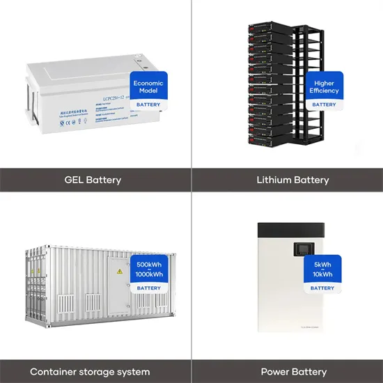
The global industrial and commercial energy storage market is experiencing explosive growth, with demand increasing by over 250% in the past two years. Containerized energy storage solutions now account for approximately 45% of all new commercial and industrial storage deployments worldwide. North America leads with 42% market share, driven by corporate sustainability initiatives and tax incentives that reduce total project costs by 18-28%. Europe follows closely with 35% market share, where standardized industrial storage designs have cut installation timelines by 65% compared to traditional built-in-place systems. Asia-Pacific represents the fastest-growing region at 50% CAGR, with manufacturing scale reducing system prices by 20% annually. Emerging markets in Africa and Latin America are adopting industrial storage solutions for peak shaving and backup power, with typical payback periods of 2-4 years. Major commercial projects now deploy clusters of 15+ systems creating storage networks with 80+MWh capacity at costs below $270/kWh for large-scale industrial applications.
Technological advancements are dramatically improving industrial energy storage performance while reducing costs. Next-generation battery management systems maintain optimal operating conditions with 45% less energy consumption, extending battery lifespan to 20+ years. Standardized plug-and-play designs have reduced installation costs from $85/kWh to $40/kWh since 2023. Smart integration features now allow multiple industrial systems to operate as coordinated energy networks, increasing cost savings by 30% through peak shaving and demand charge management. Safety innovations including multi-stage fire suppression and thermal runaway prevention systems have reduced insurance premiums by 35% for industrial storage projects. New modular designs enable capacity expansion through simple system additions at just $200/kWh for incremental capacity. These innovations have improved ROI significantly, with commercial and industrial projects typically achieving payback in 3-5 years depending on local electricity rates and incentive programs. Recent pricing trends show standard industrial systems (1-2MWh) starting at $330,000 and large-scale systems (3-6MWh) from $600,000, with volume discounts available for enterprise orders.