Sep 8, 2020 · This article explains 120° mode inverter, its circuit diagrams, output waveforms and Merits & demerits of 120° Mode inverter over 180° mode.
Aug 11, 2025 · Three Phase 180 Degree Mode VSI Question 1: In the standard three-phase voltage source inverter topology, which of the two states out of the eight valid switching states
Jul 30, 2025 · 180-degree conduction with star connected resistive load: The configuration of the three-phase inverter with star connected resistive load as shown in the figure. The following
Dec 20, 2024 · By installing a solar energy base three-phase voltage source inverter, we were able to demonstrate both the stand-alone mode and the grid-connected mode in the figure
Jul 24, 2017 · Compared to 180° and 120° conduction modes, here three phase voltage source inverter (VSI) in 150° conduction mode with a star-connected load gives 7 level, 12 steps
Jun 1, 2018 · The inverter is employed into 120° and 180° conduction modes respectively for three-phase induction motor.The system is built in the small
Nov 13, 2014 · In 180 degree mode each SCR has a duration of 180°. The SCRs of same arm operate in a complementary manner i.e with a time interval of 180° whereas the inverter arms
May 20, 2019 · In this paper we highlight the Simulink program in MATLAB for 3 phase bridge inverter for 180 degree mode. Frequency and output voltage can be changed using slider
The three-phase inverter is represented in 180-degree conduction mode because both switches S1 and S2 conduct at 180 degrees. Whereas in a full-bridge voltage source inverter all the 4
Aug 9, 2019 · To simulate Three-phase voltage source inverter for 180-degree conduction using Matlab Simulink. Three-phase inverters are normally used for high power applications. The
Oct 27, 2024 · High Voltage Applications: The 180° conduction mode inverter is suitable for applications that require higher output voltage levels, such as high
Power Transmission and Distribution: In certain cases, a 180° conduction mode inverter can be used in high-voltage DC (HVDC) systems for long-distance power transmission. It allows for efficient conversion between AC and DC power with reduced switching losses.
2. Three Phase 120° Mode Voltage Source Inverter In this conduction mode inverter, each thyristor conducts for 120° of a cycle. Like 180° mode, 120° mode inverter also requires six steps, each of 60° duration, for completing one cycle of the output AC voltage.
The three-phase inverter consists of six switches, typically arranged in a bridge configuration, and each phase is connected to a load as shown in Figure 1. The switching patterns and timing of the switches determine the shape, magnitude, and frequency of the output voltage. 1. Three Phase 180° Mode Voltage Source Inverter
Grid-Tied Systems: In grid-tied applications where the inverter is connected to the utility grid, a 180° conduction mode inverter may be used. Grid-connected inverters typically require a higher fundamental output voltage to synchronize with the grid voltage and inject power into the utility network. 2. Three Phase 120° Mode Voltage Source Inverter
• The direction of rotation of the motor can be reversed by changing the output phase sequence of the inverter. • The ac output voltage can be controlled by varying the dc-link voltage. The general configuration of a three-phase DC-AC inverter is shown in Circuit Diagram.
The current enters the load through phase c and leaves via phases a and b. Mode 6 Operation (300° - 360°) The output voltage waveform of a three-phase inverter operating in 180-degree conduction mode is characterized by its continuous and balanced nature.
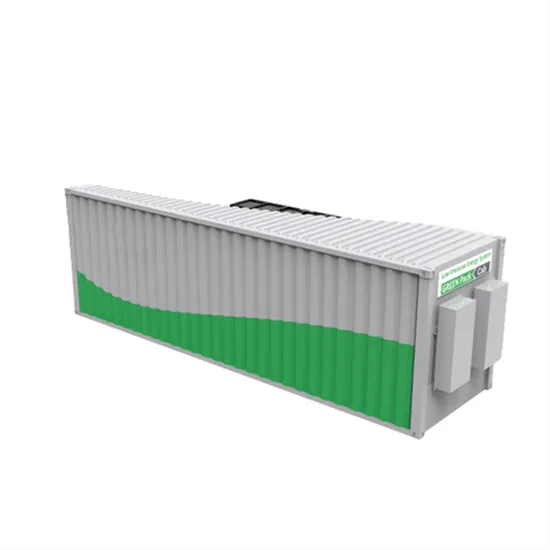
The global industrial and commercial energy storage market is experiencing explosive growth, with demand increasing by over 250% in the past two years. Containerized energy storage solutions now account for approximately 45% of all new commercial and industrial storage deployments worldwide. North America leads with 42% market share, driven by corporate sustainability initiatives and tax incentives that reduce total project costs by 18-28%. Europe follows closely with 35% market share, where standardized industrial storage designs have cut installation timelines by 65% compared to traditional built-in-place systems. Asia-Pacific represents the fastest-growing region at 50% CAGR, with manufacturing scale reducing system prices by 20% annually. Emerging markets in Africa and Latin America are adopting industrial storage solutions for peak shaving and backup power, with typical payback periods of 2-4 years. Major commercial projects now deploy clusters of 15+ systems creating storage networks with 80+MWh capacity at costs below $270/kWh for large-scale industrial applications.
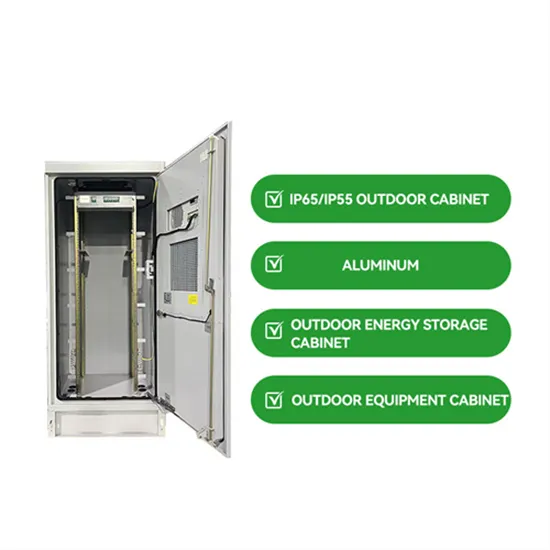
Technological advancements are dramatically improving industrial energy storage performance while reducing costs. Next-generation battery management systems maintain optimal operating conditions with 45% less energy consumption, extending battery lifespan to 20+ years. Standardized plug-and-play designs have reduced installation costs from $85/kWh to $40/kWh since 2023. Smart integration features now allow multiple industrial systems to operate as coordinated energy networks, increasing cost savings by 30% through peak shaving and demand charge management. Safety innovations including multi-stage fire suppression and thermal runaway prevention systems have reduced insurance premiums by 35% for industrial storage projects. New modular designs enable capacity expansion through simple system additions at just $200/kWh for incremental capacity. These innovations have improved ROI significantly, with commercial and industrial projects typically achieving payback in 3-5 years depending on local electricity rates and incentive programs. Recent pricing trends show standard industrial systems (1-2MWh) starting at $330,000 and large-scale systems (3-6MWh) from $600,000, with volume discounts available for enterprise orders.