Enhancing Inverter Efficiencies in Renewable
Mar 1, 2025 · In these applications, the DC-link capacitor must withstand ripple currents from both the rectifier and the inverter. Figure 5. Wind installation with
TECHNICAL SPECIFICATIONS OF ON-GRID SOLAR PV
Feb 3, 2021 · Output voltage, type of voltage (A.C. or D.C.), frequency, maximum continuous current, and for A.C. outputs, either the power or power factor for each output. The Ingress

Modern and Popular Central Inverters for Utility
Dec 25, 2023 · Almost all central inverters have common features such as maximum power point tracking, voltage & frequency regulation, reactive power
Solis Seminar 【Episode 19】: How to Section AC
Apr 28, 2021 · We need to ensure that the DC voltage loss between the PV array and the inverter is less than 3% of the output voltage of the array, and the AC
An Introduction to Inverters for Photovoltaic
Jun 3, 2020 · Inverters belong to a large group of static converters, which include many of today''s devices able to "convert" electrical parameters in input, such
Fault Current Limiting and Grid Code Compliance for Grid
Jul 8, 2024 · Grid-forming (GFM) inverters are controlled to directly regulate the voltage. A major challenge stemming from this control model is that sustaining the voltage during faults would
HITACHI SOLAR INVERTERS FOR
Apr 1, 2025 · Ensuring Grid Stability and Compliance • Grid Support Functions: Inverters equipped with grid support capabilities can help maintain voltage and frequency stability,
10 minutes Overvoltage Issue (Error 014)
Aug 17, 2025 · 1. Introduction All inverters sold within Australia are required to comply with the Australian grid standards. Under the standards, the supply voltage, the power cables, and the
On the Grid-Tied Inverter Power Limitation
Nov 7, 2018 · The power limitation of grid-tied inverter is analyzed in this paper. For the grid-tied inverter to deliver the desired power into the grid, many factors should
Why your solar inverter shuts down or reduces power?
Aug 17, 2025 · This can result in a situation where the grid voltage is complaint at 253 Volts, the AC wiring is complaint at 2% voltage rise, and the inverter is compliant at 258 volts.
Modeling and Simulation of Photovoltaic Grid
1. Introduction In recent years, due to the widespread concern of the development of solar energy resources, designing high-performance inverters has been the focus of many current research
High-voltage reinforced isolation: Definitions and test
Apr 1, 2023 · High-voltage isolation performance of an isolator is quantified at the component level by parameters such as maximum repetitive peak voltage (V IORM), working voltage (V
Inverter max VOC | Information by Electrical Professionals for
Mar 15, 2014 · And the Midnite Solar HyperVOC design for CCs already goes a long way toward doing what you are asking for. For example, it will withstand with no damage an input voltage
Impact of Grid Strength and Impedance Characteristics on
May 10, 2021 · It is revealed that power grids with a higher short circuit ratio (SCR) or lower resistance-inductance ratio (R/X) provide higher power transfer capability. Moreover, under
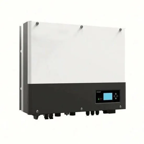
On Grid Inverter: Basics, Working Principle and Function
Jun 30, 2022 · A grid-tie inverter (GTI for short) also called on-grid inverter, which is a special inverter. In addition to converting direct current into alternating current, the output alternating
Control strategy for current limitation and maximum capacity
May 2, 2024 · Under grid voltage sags, over current protection and exploiting the maximum capacity of the inverter are the two main goals of grid-connected PV inverters. To facilitate low
Introduction on technical guidelines for utilities
Oct 21, 2020 · The maximum number of modules in a string is determined by dividing the maximum allowable input voltage of the inverter by the effective maximum open circuit voltage
Fault-induced current limitation control for grid-forming inverters
May 1, 2025 · This paper presents a current limitation scheme for a grid-forming inverter-based resource (IBR). The proposed controller allows the IBR to be integrated into distribution
How to Read Solar On Grid Inverter Data Sheet?
Dec 10, 2019 · Like CE or UL. etc. Reading and understanding a solar on grid inverter data sheet is crucial for selecting the right inverter for your solar power system. By familiarizing
Selecting IGBTs for High-Efficiency Grid-Tied Inverters
Jun 17, 2025 · Voltage Rating (V CES) This is the maximum voltage the IGBT can block when it is in the "off" state. The rule of thumb is to select a voltage rating for the IGBT inverter with a
How to Select the Right Inverter Duty Transformer
An essential but underrepresented component of the systems is the inverter duty transformer. These transformers act as a connection between the inverter and the grid or the load so as to
6 FAQs about [The maximum grid voltage that the inverter can withstand]
What factors should be considered when choosing a grid-tied inverter?
For the grid-tied inverter to deliver the desired power into the grid, many factors should be taken into account, including the dc input voltage, the grid voltage, component current rating, and the output inductor. The inverter output voltage amplitude is limited by the input dc voltage source to prevent the over modulation problem.
What if the average grid voltage exceeds 260 volts?
The average grid voltage (UAC) at the inverter as measured over a period of 10 minutes is limited to a maximum of 253 V in Germany according to DIN VDE 0126-1-1. If the inverter records that the 10-minute average exceeds this voltage limit, or if the 260 V limit is temporarily exceeded, it will switch off immediately.
What happens if an inverter exceeds the voltage limit?
If the inverter records that the 10-minute average exceeds this voltage limit, or if the 260 V limit is temporarily exceeded, it will switch off immediately. The inverter will display a grid error message if this occurs.
What are the goals of grid-connected PV inverters?
Under grid voltage sags, over current protection and exploiting the maximum capacity of the inverter are the two main goals of grid-connected PV inverters. To facilitate low-voltage ride-through (LVRT), it is imperative to ensure that inverter currents are sinusoidal and remain within permissible limits throughout the inverter operation.
How do grid-tied PV inverters work?
When a fault (such as a short circuit, flickering, or loss of grid power) occurs on the grid, even if it is transient in nature, the conventional grid-tied PV inverters automatically cut themselves off from the grid. The inverters are configured in this fashion to prevent damage from transients of over current or over voltage.
How to provide voltage support in PV inverter?
To provide voltage support at the PCC, reactive power is injected into the grid under fault conditions as per the specified grid codes. As previously discussed, the simultaneous injection of peak active power from PVs and reactive power into the grid for voltage support can trigger the over current protection mechanism in PV inverter.
Learn More
- Inverter high voltage grid connection
- The maximum voltage output by the inverter
- What is the maximum voltage of a 48v inverter
- Argentina voltage stabilizer inverter manufacturer
- 5kw on grid inverter in China in Auckland
- How big is the impact of connecting the inverter of the communication base station to the grid
- On grid inverter 5kw in China in Cebu
- Power inverter grid cabinet
- Can the DC 12V voltage be supplied to the inverter
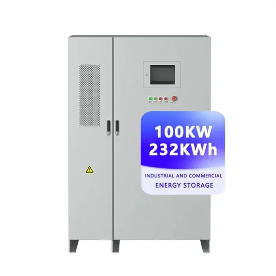
Industrial & Commercial Energy Storage Market Growth
The global industrial and commercial energy storage market is experiencing explosive growth, with demand increasing by over 250% in the past two years. Containerized energy storage solutions now account for approximately 45% of all new commercial and industrial storage deployments worldwide. North America leads with 42% market share, driven by corporate sustainability initiatives and tax incentives that reduce total project costs by 18-28%. Europe follows closely with 35% market share, where standardized industrial storage designs have cut installation timelines by 65% compared to traditional built-in-place systems. Asia-Pacific represents the fastest-growing region at 50% CAGR, with manufacturing scale reducing system prices by 20% annually. Emerging markets in Africa and Latin America are adopting industrial storage solutions for peak shaving and backup power, with typical payback periods of 2-4 years. Major commercial projects now deploy clusters of 15+ systems creating storage networks with 80+MWh capacity at costs below $270/kWh for large-scale industrial applications.
Industrial Energy System Innovations & Cost Benefits
Technological advancements are dramatically improving industrial energy storage performance while reducing costs. Next-generation battery management systems maintain optimal operating conditions with 45% less energy consumption, extending battery lifespan to 20+ years. Standardized plug-and-play designs have reduced installation costs from $85/kWh to $40/kWh since 2023. Smart integration features now allow multiple industrial systems to operate as coordinated energy networks, increasing cost savings by 30% through peak shaving and demand charge management. Safety innovations including multi-stage fire suppression and thermal runaway prevention systems have reduced insurance premiums by 35% for industrial storage projects. New modular designs enable capacity expansion through simple system additions at just $200/kWh for incremental capacity. These innovations have improved ROI significantly, with commercial and industrial projects typically achieving payback in 3-5 years depending on local electricity rates and incentive programs. Recent pricing trends show standard industrial systems (1-2MWh) starting at $330,000 and large-scale systems (3-6MWh) from $600,000, with volume discounts available for enterprise orders.
