Dec 5, 2023 · 500w Power Inverter Circuit Using Sg3526 Irfp540 How To Build An Inverter Ranging From 250 Watts 5000 Science Technology Nigeria Pwm Inverter Circuit Based On
Jul 16, 2016 · The design of the sine wave inverter based on full-bridge inverter circuit, SG3525 chip, and integrated SPWM chip has been used as control core. The design includes the
The sine wave oscillator, precision rectifier circuit, 50HZ synchronous wave generating circuit, adding circuit, etc. are basically the same as those in the previous post, without major
Sep 9, 2024 · The SG3525 inverter circuit offers a versatile and efficient solution for generating both modified and pure sine wave AC outputs. It operates using a basic PWM technique to
Mar 1, 2025 · First disconnect the jumper JP1 to open the circuit loop, adjust VR1 to make the output sine wave not clipped; adjust VR2 to make the upper and lower half waves of the sine
Nov 12, 2020 · Design Of Single Phase Sine Wave Spwm Inverter Power Supply Based On Sg3525 Electronics Engineering World Introduction To Sg3525 Is A Pulse Width Modulated
Dec 19, 2024 · In this article I have explained comprehensively regarding how to design a sine wave inverter without any form of coding or complex circuit
Jun 17, 2023 · In this article, we will discuss how to use the SG3525 in order to create a pure sine wave inverter circuit diagram. We will also discuss the
Sep 25, 2024 · Design of single phase sine wave spwm inverter power supply based on sg3525 dspic33f microcontroller pure how to make a simple 100w high frequency printed circuit
Apr 24, 2020 · SG3525 Applications It is used for power electronics applications like pure sine wave inverters. It is used to generate regulated voltage for dc to
Jan 3, 2024 · Device portability is significant challenge in designing high-power inverters. This research uses a ferrite core transformer to design a portable pure sine wave inverter.
Abstract.This paper designs a sine wave inverter that converts 12V DC into 220V/50Hz AC. In the DC/DC converter circuit, the push-pull circuit is used for boosting. The pulse width modulator
First disconnect the jumper JP1 to open the circuit loop, adjust VR1 to make the output sine wave not clipped; adjust VR2 to make the upper and lower half waves of the sine wave connect
The SG3525 is a popular integrated circuit that is widely used in the design of sinusoidal pulse width modulation (PWM) inverters. The circuit diagram of a pure sine wave inverter using the SG3525 is relatively simple. It consists of an SG3525 chip, a few electrical components such as resistors, capacitors, and diodes, and a power transformer.
However even for an SPWM, the RMS value will need to be correctly set initially in order to produce the correct voltage output at the output of the transformer. Once implemented one can expect a real sine wave equivalent output from any SG3525 inverter design or may be from any square wave inverter model.
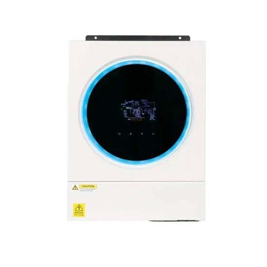
The SG3525 is a versatile PWM (Pulse Width Modulation) controller IC commonly present in inverter circuits to convert DC to AC at either 50Hz or 60Hz. Here’s a PWM based SG3525 inverter circuit with working. 1. Components Required: 2. Circuit Description:
The sg3525 is a pulse width modulation (PWM) controller that is commonly used in inverter circuits. It generates a square wave signal that can be modified to produce a sine wave output. The inverter circuit diagram typically consists of the sg3525 controller, a power stage, and a feedback loop.
The pure sine wave inverter circuit diagram using SG3525 consists of several basic components, including the SG3525 IC itself, a power MOSFET (Metal-Oxide-Semiconductor Field-Effect Transistor), a step-up transformer, a filter capacitor, and an output socket. The SG3525 IC receives a DC input voltage and generates a PWM signal.
The "chopping" is done by feeding a calculated PWM to the gates of the FET via a BJT buffer stage. A typical circuit design for converting the SG3525 waveform into a pure sine wave waveform is shown below. This design is actually an universal design which may be implemented for upgrading all square wave inverters into sine wave inverters.
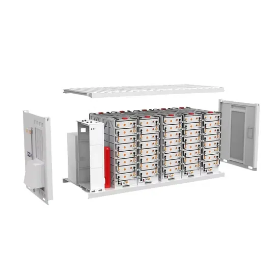
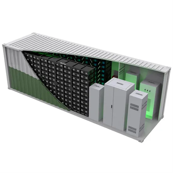
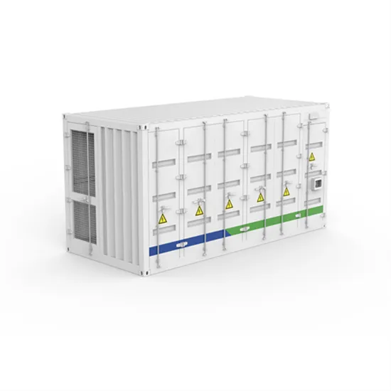
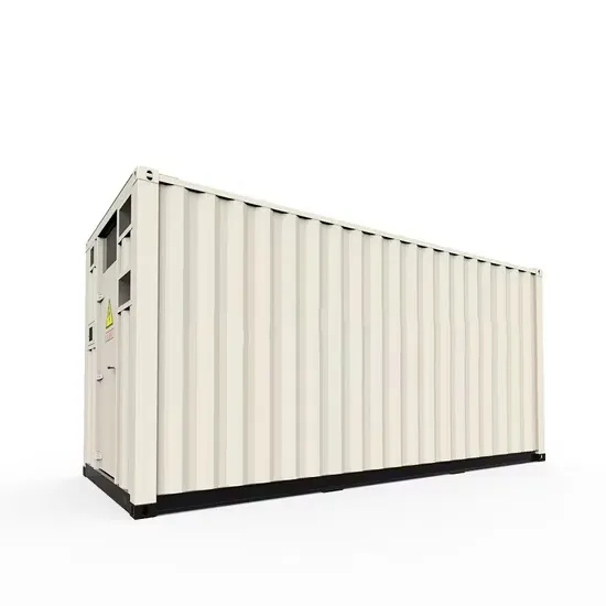
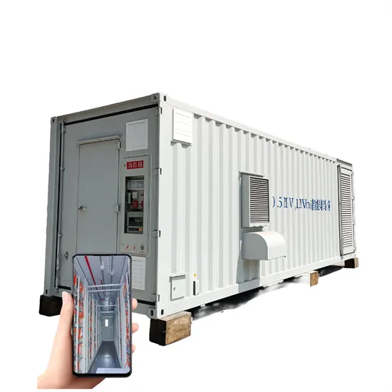
The global industrial and commercial energy storage market is experiencing explosive growth, with demand increasing by over 250% in the past two years. Containerized energy storage solutions now account for approximately 45% of all new commercial and industrial storage deployments worldwide. North America leads with 42% market share, driven by corporate sustainability initiatives and tax incentives that reduce total project costs by 18-28%. Europe follows closely with 35% market share, where standardized industrial storage designs have cut installation timelines by 65% compared to traditional built-in-place systems. Asia-Pacific represents the fastest-growing region at 50% CAGR, with manufacturing scale reducing system prices by 20% annually. Emerging markets in Africa and Latin America are adopting industrial storage solutions for peak shaving and backup power, with typical payback periods of 2-4 years. Major commercial projects now deploy clusters of 15+ systems creating storage networks with 80+MWh capacity at costs below $270/kWh for large-scale industrial applications.
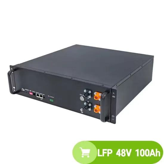
Technological advancements are dramatically improving industrial energy storage performance while reducing costs. Next-generation battery management systems maintain optimal operating conditions with 45% less energy consumption, extending battery lifespan to 20+ years. Standardized plug-and-play designs have reduced installation costs from $85/kWh to $40/kWh since 2023. Smart integration features now allow multiple industrial systems to operate as coordinated energy networks, increasing cost savings by 30% through peak shaving and demand charge management. Safety innovations including multi-stage fire suppression and thermal runaway prevention systems have reduced insurance premiums by 35% for industrial storage projects. New modular designs enable capacity expansion through simple system additions at just $200/kWh for incremental capacity. These innovations have improved ROI significantly, with commercial and industrial projects typically achieving payback in 3-5 years depending on local electricity rates and incentive programs. Recent pricing trends show standard industrial systems (1-2MWh) starting at $330,000 and large-scale systems (3-6MWh) from $600,000, with volume discounts available for enterprise orders.