May 5, 2025 · Some problems with photovoltaic projects for household applications are the cost, efficiency and complexity of the inverter. Various inverter topologies are used but do not
May 6, 2023 · Circuit Diagram of Single-Phase Full Bridge Inverter: The power circuit of a single-phase full bridge inverter comprises of four thyristors T1 to T4, four diodes D1 to D1 and a two
Jun 25, 2020 · Abstract— A Sine PWM inverter needs an output filter for elimination of the carrier frequency components. Here LC filter is presented. The process of selection of L and C
Jul 30, 2025 · This paper introduces a novel 13-level switched capacitor inverter. The proposed structure, comprising ten switches, five diodes, one input DC source, and five capacitors, can
Oct 24, 2008 · Hello A true-sinewave inverter cost too much for me. So I have a Xantrex XPower 1000 inverter. This 1000 watt inverter do have a modified sinewave output. Is it possible to
The circuit of a multiphase parallel resonant inverter with a pure sine wave output voltage is proposed. The operating principle of the two-phase inverter and the method of output voltage
May 16, 2023 · A thirteen-level inverter based on switching capacitor is proposed in order to improve the boost capacity and output power quality of inverter in
Dec 19, 2024 · In this article I have explained comprehensively regarding how to design a sine wave inverter without any form of coding or complex circuit
Nov 30, 2020 · o switched-capacitor inverter is used which generates multilevel voltage w th switching capacitors in series or parallel. Working topology of switched capacitor and charge
Nov 29, 2022 · Inverters output an AC signal that is typically either a sine wave, square wave, or modified quasi-sine wave, depending on the application. Inverter signal outputs that aim to
Dec 18, 2024 · 1.2 Inverter types A broad definition of an inverter is a power converter that converts a DC input to an AC output. For most applications, a pure sine wave output is
Apr 1, 2023 · The Modified Square Wave also known as the Modified Sine Wave Inverter produces square waves with some dead spots between positive and negative half-cycles at
Apr 1, 2023 · Here H-bridge circuit converts battery DC voltage into AC using high frequency PWM (6 kHz to 20 KHz) thus feeding the 50-Hz transformer which Boost it to 120V/220V AC.
Oct 12, 2019 · Definition of dv / dt: PWM-Signal and single pulse at the inverter output In the case of short motor cables (up to about 20 m), these rise times – ow-ing to the small line impedance
Mar 3, 2004 · How do designs that transform dc-ac sinewave handle the return energy of a reactive load. I know the basic building block of an inverter is an H bridge with a filter after,
May 26, 2021 · The big caps in an inverter smooth out pulses of current drawn by high frequency step up SMPS (HF inverters) and store the boosted voltage (HF inverters), They smooth the
Feb 9, 2009 · An inductor as a lowpass filter has resistance that will reduce the output voltage of the inverter too much. A pure sine-wave inverter does not start with a stepped square-wave
A very effective pure sine wave inverter circuit can be made using the IC 4047 and a couple IC 555 together with a few other passive components. I have explained the details below.
The sine wave output is obtained by forming a tank circuit with the secondary winding of the inverter transformer in parallel with capacitors C5 through C7. Two 2.2µF capacitors are connected to the gates of the MOSFETs in both banks with respect to the ground if proper sinewave is not produced.
At present, the current sharing control strategies for parallel operation of inverters (such as 2000w inverter or 3000w inverter) mainly include: current detection loop method; master-slave parallel control method, decentralized logic control method, and external characteristic droop parallel control method.
Some of them produce a square-wave output, which is undesirable for inductive loads. Here we designed a simple sine wave inverter circuit that produces 50Hz quasi-sine wave output using a single IC CD4047 and some discrete components, which makes it a very cost-effective solution. The DIY sine wave inverter circuit using IC 4047 is given below.
This way an alternating output voltage is obtained across the secondary winding. The sine wave output is obtained by forming a tank circuit with the secondary winding of the inverter transformer in parallel with capacitors C5 through C7.
There must be a simple methods and hardware, hopefully off-the-shelf device/circuit board/etc, to do the syncing of inverter outputs. Yes? No? Maybe? Usually this requires synchronizing the frequency generator signal inside of the inverters. Most inverters do not have this capability.
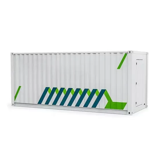
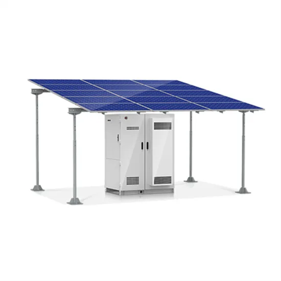
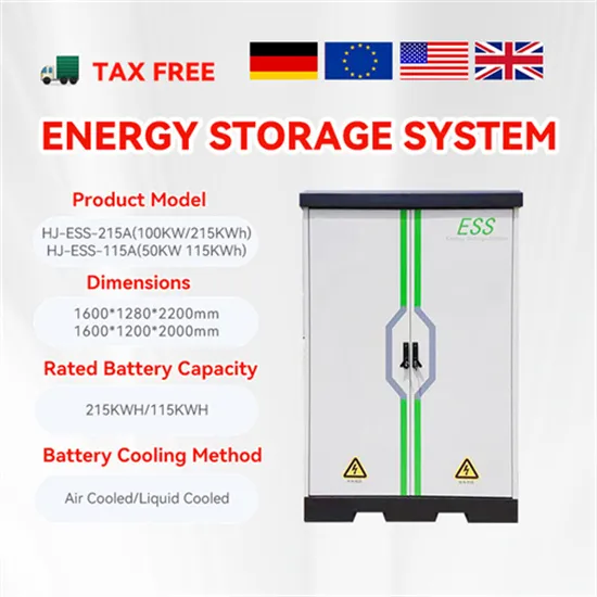
The global industrial and commercial energy storage market is experiencing explosive growth, with demand increasing by over 250% in the past two years. Containerized energy storage solutions now account for approximately 45% of all new commercial and industrial storage deployments worldwide. North America leads with 42% market share, driven by corporate sustainability initiatives and tax incentives that reduce total project costs by 18-28%. Europe follows closely with 35% market share, where standardized industrial storage designs have cut installation timelines by 65% compared to traditional built-in-place systems. Asia-Pacific represents the fastest-growing region at 50% CAGR, with manufacturing scale reducing system prices by 20% annually. Emerging markets in Africa and Latin America are adopting industrial storage solutions for peak shaving and backup power, with typical payback periods of 2-4 years. Major commercial projects now deploy clusters of 15+ systems creating storage networks with 80+MWh capacity at costs below $270/kWh for large-scale industrial applications.
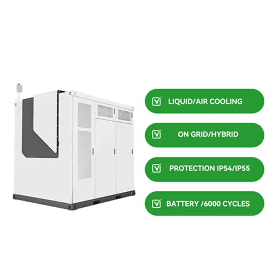
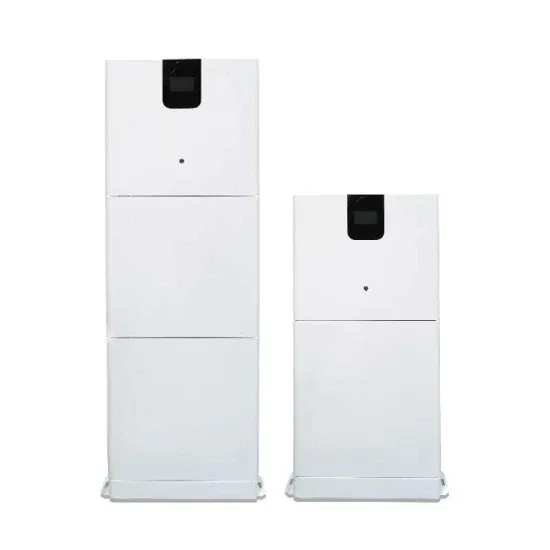
Technological advancements are dramatically improving industrial energy storage performance while reducing costs. Next-generation battery management systems maintain optimal operating conditions with 45% less energy consumption, extending battery lifespan to 20+ years. Standardized plug-and-play designs have reduced installation costs from $85/kWh to $40/kWh since 2023. Smart integration features now allow multiple industrial systems to operate as coordinated energy networks, increasing cost savings by 30% through peak shaving and demand charge management. Safety innovations including multi-stage fire suppression and thermal runaway prevention systems have reduced insurance premiums by 35% for industrial storage projects. New modular designs enable capacity expansion through simple system additions at just $200/kWh for incremental capacity. These innovations have improved ROI significantly, with commercial and industrial projects typically achieving payback in 3-5 years depending on local electricity rates and incentive programs. Recent pricing trends show standard industrial systems (1-2MWh) starting at $330,000 and large-scale systems (3-6MWh) from $600,000, with volume discounts available for enterprise orders.