Dec 18, 2024 · A very simple low battery cut-off and overload protection circuit has been explained here. The figure shows a very simple circuit set up which

May 20, 2022 · 1. Input overvoltage protection: When the input voltage of the DC side is higher than the maximum allowable DC array access voltage of the grid-tied inverter, the inverter
Jul 2, 2025 · High voltage protection of the inverter: The default charging voltage of Xindun Power''s inverter is: 14.2vdc/cell. When the battery reaches this voltage value, the inverter will
May 18, 2025 · IR''s monolithic high voltage technology allows the IR2x14 and IR2x141 families to safely drive 110Vac to 380Vac applications and provide capability to withstand up to 600Vdc or
Jun 4, 2021 · I will examine the inverter protection mechanisms used to keep dc-side and ac-side faults from causing damage to the inverter. Inverter grid supporting functions, along with
* for protection Features: Designed with multiple safety measures including over-voltage, short-circuit, and over-current for protection, this inverter ensures reliable and stable performance

May 1, 2021 · Abstract: Inverter is a power electronic circuit that converts the direct voltage (DC) to an alternating voltage (AC). Inverters are used in a range of applications from consumer
However, in areas with extreme or frequent voltage instability, using an external stabiliser can provide additional protection and ensure smooth operation. Do inverters have overload
Sep 22, 2022 · The inverter voltage control characteristic can be combined with a plant controller to provide Point of Interconnection (POI) voltage controls that
Dec 6, 2017 · The information on the IGBT inverter, IGBT gate driver, onboard power supply, and fault protection feature are given in the design guide Reference Design for Reinforced Isolation
Apr 1, 2023 · Besides, three-level inverter topology makes it possible to use the same switching device to support this much higher voltage stress than before. However, compared with
May 11, 2022 · Lower system cost is achieved by using the AMC1301 to measure motor current interfaced with internal ADC of MCU and use of bootstrap power supply for IGBT gate drivers.
Aug 27, 2024 · Discover common misconceptions about grid-tied inverters in solar PV systems, including voltage output, anti-islanding protection, and DC string voltage effects.
Jun 7, 2020 · There are a lot of power converter topologies for PV systems such as two-stage, single-stage, with transformer, transformerless and others. However all these topologies
May 11, 2022 · The three-phase inverter uses insulated gate bipolar transistor (IGBT) switches which have advantages of high input impedance as the gate is insulated, has a rapid response
Aug 19, 2025 · What will I get out of this session? Purpose: To provide an overview of complete high voltage power solutions in DC-DC Conversions and Tractions Inverters Introduction
May 11, 2022 · Apart from isolated gate-drivers for IGBTs, the three-phase inverters include DC bus voltage sensing, inverter current sensing, IGBT protection (like over-temperature,
Design a Single Phase Inverter and a Three Phase Inverter with Protection Circuits in Proteus Samhar Saeed Shukir Department of Electrical Department, Technical Institute- Kut, Middle
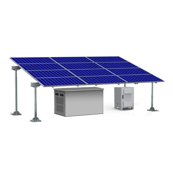
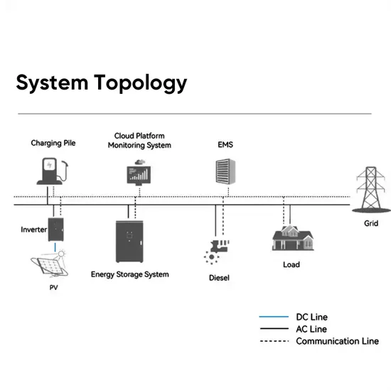
Inverters are core devices in scenarios like photovoltaic power generation and electric vehicle charging, and their safe operation depends on various protection mechanisms. This article will
This article will introduce the multiple protection mechanisms of the inverter in detail, including voltage protection, current protection, temperature protection, short circuit protection, reverse
A three-phase traction inverter is used to convert DC input to three-phase AC output and is located between the high-voltage battery and the electrical load (motor). Short-circuit events in
Without proper protection, an inverter can be damaged by power surges, voltage spikes, and other electrical disturbances. There are several types of protection that can be used to protect inverters: Surge protection: This type of protection is designed to protect the inverter from power surges and voltage spikes.
This protection mechanism effectively safeguards the inverter and load devices from the hazards of short circuit faults. 3.Overvoltage Protection: The inverter not only monitors the stability of the input voltage but also recognizes excessively high input voltages.
Surge protection: This type of protection is designed to protect the inverter from power surges and voltage spikes. Overload protection: This type of protection is designed to protect the inverter from being overloaded. Under-voltage protection: This type of protection is designed to protect the inverter from low voltage.
Inverters equipped with over- and under-voltage protection automatically monitor the input and output voltage levels. If the voltage deviates from the preset safe range, the inverter will either shut down or adjust its output to bring the voltage back within acceptable limits.
Protection against these involves the use of circuit breakers and fuses that automatically disconnect the circuit when excessive current is detected. These protective devices must be installed on both the AC and DC sides of the inverter. They operate by breaking the circuit, thus stopping the flow of electricity and preventing damage.
Under normal circumstances, the inverter will provide a power supply of 2.5 kW based on the load requirements of the device. However, if you add another load that increases the load current beyond the rated capacity of the inverter, for example, 3.5 kW, the overload protection mechanism of the inverter will be triggered.
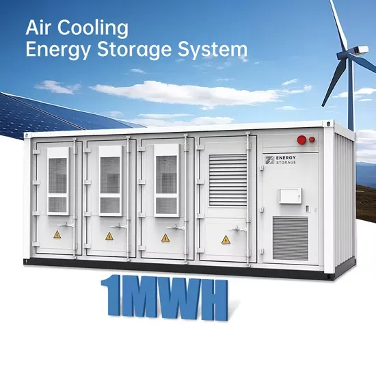
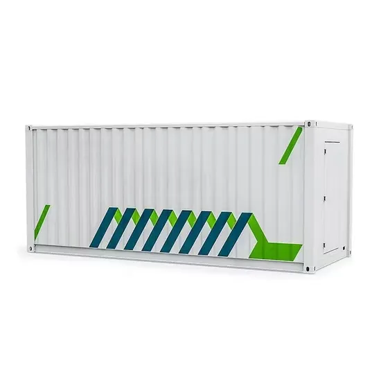
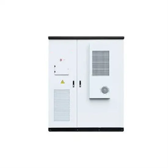
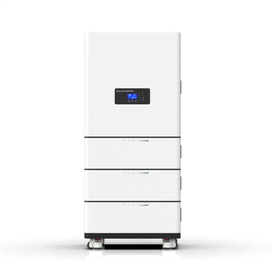
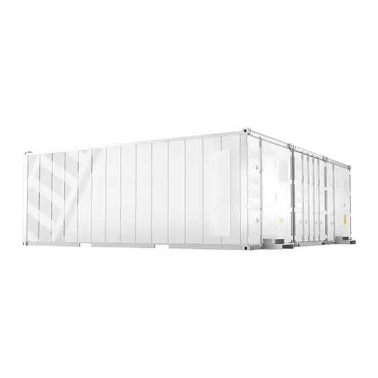
The global industrial and commercial energy storage market is experiencing explosive growth, with demand increasing by over 250% in the past two years. Containerized energy storage solutions now account for approximately 45% of all new commercial and industrial storage deployments worldwide. North America leads with 42% market share, driven by corporate sustainability initiatives and tax incentives that reduce total project costs by 18-28%. Europe follows closely with 35% market share, where standardized industrial storage designs have cut installation timelines by 65% compared to traditional built-in-place systems. Asia-Pacific represents the fastest-growing region at 50% CAGR, with manufacturing scale reducing system prices by 20% annually. Emerging markets in Africa and Latin America are adopting industrial storage solutions for peak shaving and backup power, with typical payback periods of 2-4 years. Major commercial projects now deploy clusters of 15+ systems creating storage networks with 80+MWh capacity at costs below $270/kWh for large-scale industrial applications.
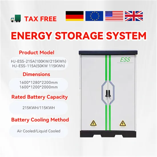
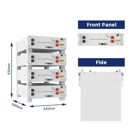
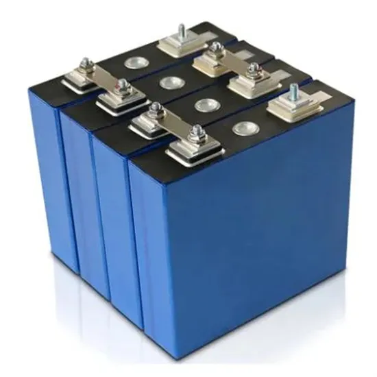
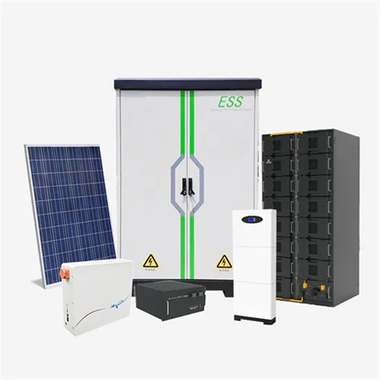
Technological advancements are dramatically improving industrial energy storage performance while reducing costs. Next-generation battery management systems maintain optimal operating conditions with 45% less energy consumption, extending battery lifespan to 20+ years. Standardized plug-and-play designs have reduced installation costs from $85/kWh to $40/kWh since 2023. Smart integration features now allow multiple industrial systems to operate as coordinated energy networks, increasing cost savings by 30% through peak shaving and demand charge management. Safety innovations including multi-stage fire suppression and thermal runaway prevention systems have reduced insurance premiums by 35% for industrial storage projects. New modular designs enable capacity expansion through simple system additions at just $200/kWh for incremental capacity. These innovations have improved ROI significantly, with commercial and industrial projects typically achieving payback in 3-5 years depending on local electricity rates and incentive programs. Recent pricing trends show standard industrial systems (1-2MWh) starting at $330,000 and large-scale systems (3-6MWh) from $600,000, with volume discounts available for enterprise orders.