Filters & Wave Shaping
Jun 3, 2020 · Sine Waves A graph of the rate of change of a sine wave is another sine wave that has undergone a 90° phase shift (with the output wave leading the input wave). Square Waves
Introduction to inverters: structure, operating
May 24, 2024 · Discover the basics of inverters - their structure, operating principles, and functions. Explore Junchipower''s expertise in this informative
Design and Implementation of Single Phase Pure Sine
Mar 16, 2015 · Design & Implementation of Single Phase Pure Sine Wave Inverter Using Multivibrator IC Meraj Hasan*, Junaid Maqsood*, Mirza Qutab Baig*, Syed Murtaza Ali Shah
Optimization of an OTA Based Sine Waveshaper
Feb 2, 2017 · This paper briefly discusses some of the most popular ways of converting a triangle wave to a sine wave, and goes into depth on one the lowest distortion options, the Operational
Simple Modified Sine Wave Inverter Circuit
Nov 21, 2018 · Modified Sine Wave Inverter Circuit In this article we will build a modified sine wave inverter circuit utilizing IC 555 and IC 4017. Modified sine
800VA Pure Sine Wave Inverter''s Reference Design (Rev
Apr 1, 2023 · The pure Sine Wave inverter has various applications because of its key advantages such as operation with very low harmonic distortion and clean power like utility-supplied
CHAPTER 3: OSCILLATORS AND WAVEFORM-SHAPING
Jun 26, 2012 · I. SINUSOIDALOSCILLATORS: Commonlyreferred to aslinear sine-wave oscillatorsalthoughsome formsofnon-linearity havetobeemployedtolimittheoutputamplitude

AN-CM-374 Sine Wave Based Inverter
Jan 31, 2024 · This app note describes how the AnalogPAK SLG47004 can be used as the core of a sine wave-based inverter useful for automotive and renewable energies application.
Signal Generators and Waveform-Shaping Circuits
Sep 27, 2005 · A sine wave is obtained by shaping a triangular waveform. Circuits that generate square, triangular, pulse, etc., are called oscillators or function generators, employ circuit
H Bridge Inverter Circuit using IC SG3525 and
Jan 9, 2025 · Conclusion The SG3525-based H-bridge inverter circuit is a reliable and efficient solution for converting DC voltage to AC power. With features
6 FAQs about [Sine wave inverter IC shaping]
How to make a pure sine wave inverter circuit?
A very effective pure sine wave inverter circuit can be made using the IC 4047 and a couple IC 555 together with a few other passive components. I have explained the details below.
Can a sine wave inverter produce a square wave output?
Some of them produce a square-wave output, which is undesirable for inductive loads. Here we designed a simple sine wave inverter circuit that produces 50Hz quasi-sine wave output using a single IC CD4047 and some discrete components, which makes it a very cost-effective solution. The DIY sine wave inverter circuit using IC 4047 is given below.
Can Proteus simulate a pure sine wave inverter circuit?
However, when you connect an LC filter at the output of the H Bridge, Proteus will not simulate your circuit. We suggest you make this circuit on hardware and verify the results. In conclusion, this article provided a comprehensive overview of how to create a pure sine wave inverter circuit diagram.
What is a sine wave in a power inverter?
The sine wave is a fundamental waveform that is used in various applications, including power inverters. A power inverter is an electronic device that converts direct current (DC) to alternating current (AC) to power appliances and devices that require AC power.
What is a modified square wave inverter?
The Modified Square Wave also known as the Modified Sine Wave Inverter produces square waves with some dead spots between positive and negative half-cycles at the output. The cleanest utility supply like power source is provided by Pure Sine Wave inverters.
What is sine wave conversion?
You might be curious to know regarding what exactly happens in the process of the conversion which transforms the output into a pure sine wave suitable for all sensitive electronic loads. It is basically done by optimizing the sharp rising and falling square wave pulses into a gently rising and falling waveform.
Learn More
- Zhenneng pure sine wave inverter
- Moscow Split Phase Sine Wave Inverter
- 5v inverter produces sine wave
- Swaziland pure sine wave inverter supply
- High frequency pure sine wave inverter
- Pure sine wave 6000w inverter price
- 3525 inverter converted to pure sine wave
- Pure sine wave inverter price in Azerbaijan
- Sine wave inverter
Industrial & Commercial Energy Storage Market Growth
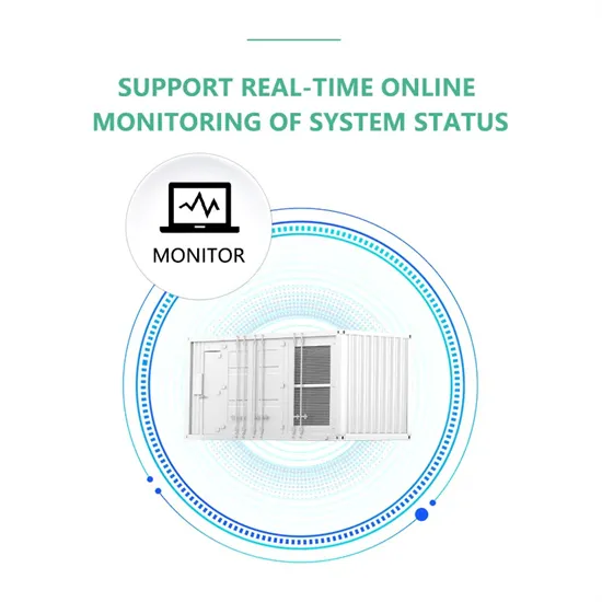
The global industrial and commercial energy storage market is experiencing explosive growth, with demand increasing by over 250% in the past two years. Containerized energy storage solutions now account for approximately 45% of all new commercial and industrial storage deployments worldwide. North America leads with 42% market share, driven by corporate sustainability initiatives and tax incentives that reduce total project costs by 18-28%. Europe follows closely with 35% market share, where standardized industrial storage designs have cut installation timelines by 65% compared to traditional built-in-place systems. Asia-Pacific represents the fastest-growing region at 50% CAGR, with manufacturing scale reducing system prices by 20% annually. Emerging markets in Africa and Latin America are adopting industrial storage solutions for peak shaving and backup power, with typical payback periods of 2-4 years. Major commercial projects now deploy clusters of 15+ systems creating storage networks with 80+MWh capacity at costs below $270/kWh for large-scale industrial applications.
Industrial Energy System Innovations & Cost Benefits
Technological advancements are dramatically improving industrial energy storage performance while reducing costs. Next-generation battery management systems maintain optimal operating conditions with 45% less energy consumption, extending battery lifespan to 20+ years. Standardized plug-and-play designs have reduced installation costs from $85/kWh to $40/kWh since 2023. Smart integration features now allow multiple industrial systems to operate as coordinated energy networks, increasing cost savings by 30% through peak shaving and demand charge management. Safety innovations including multi-stage fire suppression and thermal runaway prevention systems have reduced insurance premiums by 35% for industrial storage projects. New modular designs enable capacity expansion through simple system additions at just $200/kWh for incremental capacity. These innovations have improved ROI significantly, with commercial and industrial projects typically achieving payback in 3-5 years depending on local electricity rates and incentive programs. Recent pricing trends show standard industrial systems (1-2MWh) starting at $330,000 and large-scale systems (3-6MWh) from $600,000, with volume discounts available for enterprise orders.
