Feb 13, 2024 · The input to an H-bridge is a DC voltage source and the output is also a DC voltage, but whose magnitude and polarity can be controlled. The converter can be used to
Aug 25, 2020 · This is implemented through an H-bridge inverter stage, which converts this high frequency into output into the desired 220V AC. However,
Jun 30, 2025 · So here basically we are using two IR2184 ICs for driving two half-bridge stages which finally together become a full H-bridge inverter. This inverter is converting 220V DC into
Apr 1, 2023 · The DC-AC section consists of high-side and low-side drivers to drive the Mosfets in the H-Bridge configuration followed by an output L-C- L filter resulting in sinusoidal sine wave.
Oct 1, 2018 · In both the aforementioned topologies, the rectified sine wave current obtained in the first stage is converted into the full wave sinusoidal current at the line-frequency switching by
May 24, 2025 · The proposed Arduino inverter circuit could be upgraded to any preferred higher wattage level, simply by upgrading the mosfets and the trafo
Dec 19, 2024 · In this article I have explained comprehensively regarding how to design a sine wave inverter without any form of coding or complex circuit
Apr 1, 2023 · The pure Sine Wave inverter has various applications because of its key advantages such as operation with very low harmonic distortion and clean power like utility-supplied
Dec 22, 2005 · In this post we''ll discuss how to convert any ordinary square wave H-bridge inverter into an almost pure sine wave inverter circuit. The idea is simple, just chop the low

Jun 1, 2024 · An experimental single-phase H-bridge inverter, controlled by two PWM signals generated by a microcontroller via two drivers, has been designed and fabricated as shown in
Jun 18, 2025 · The design adopts a full-bridge inverter topology utilizing high-efficiency MOSFET switches, a step-up transformer, and an LC low-pass filter to produce a 230V, 50Hz pure sine
Oct 13, 2014 · I know how a half bridge and full bridge circuit looks like. What I don''t understand (and I simulated it) is that whenever I drive the switches
Apr 1, 2023 · This application report documents the implementation of the Voltage Fed Full Bridge isolated DC-DC converter followed by the Full-Bridge DC-AC converter using TMS320F28069
The project was funded by IEEE PES with a view to design 1KW Pure Sine Wave Inverter. This was my first power electronics project using off-the-shelf components
Apr 27, 2025 · In [4] and [5], Boost and Buck are combined with H-bridge structures for AC motor drives, respectively. The front-stage DC-DC converter provides a sinusoidal half-wave and the
Jul 15, 2018 · A need for power rating inverter is required to smoothly operate electrical and electronic appliances. Most of the commercially available UPS or IPS is actually square wave
Aug 4, 2025 · In this post I have explained a 3 powerful yet simple sine wave 12V inverter circuits using a single IC SG 3525. The first circuit is equipped with a
Aug 3, 2024 · In this post we''ll discuss how to convert any ordinary square wave H-bridge inverter into an almost pure sine wave inverter circuit. The idea is
The SG3525-based H-bridge inverter circuit is a reliable and efficient solution for converting DC voltage to AC power. With features such as voltage regulation and low battery protection, it is suitable for powering a wide range of devices.
The simplest form of an inverter is the bridge-type, where a power bridge is controlled according to the sinusoidal pulse-width modulation (SPWM) principle and the resulting SPWM wave is filtered to produce the alternating output voltage. In many applications, it is important for an inverter to be lightweight and of a relatively small size.
The SG3525-based H-Bridge inverter circuit converts low-voltage DC into high-voltage AC, making it ideal for use in applications like renewable energy systems, backup power supplies, and portable inverters. Below is a detailed description of the circuit components and their roles. You can also see block diagram of SPWM inverter circuit.
In many applications, it is important for an inverter to be lightweight and of a relatively small size. This can be achieved by using a High-Frequency Inverter that involves an isolated DC-DC stage (Voltage Fed Push-Pull/Full Bridge) and the DC-AC section, which provides the AC output.
H-Bridge MOSFET Power Stage The H-bridge stage consists of four N-channel MOSFETs (e.g., IRFZ44N), which switch the DC voltage across the transformer’s primary winding to generate an alternating waveform. Gate Resistors: Resistors are connected to the MOSFET gates to limit the gate charging current and prevent ringing.
Below is an overview of the primary elements: SG3525 IC: The main controller for generating PWM signals to drive the MOSFETs in the H-bridge configuration. H-Bridge MOSFETs: Power transistors (typically N-channel MOSFETs such as IRFZ44N or IRF3205) that switch the DC voltage to generate an alternating waveform.
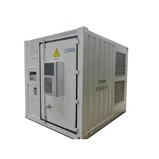
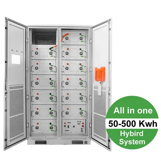
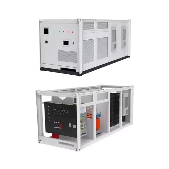
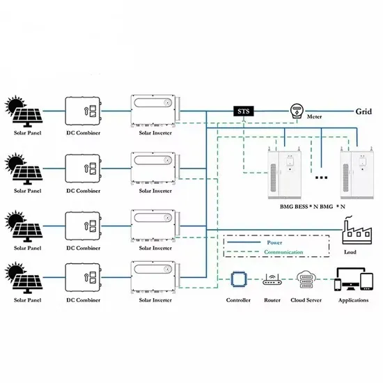
The global industrial and commercial energy storage market is experiencing explosive growth, with demand increasing by over 250% in the past two years. Containerized energy storage solutions now account for approximately 45% of all new commercial and industrial storage deployments worldwide. North America leads with 42% market share, driven by corporate sustainability initiatives and tax incentives that reduce total project costs by 18-28%. Europe follows closely with 35% market share, where standardized industrial storage designs have cut installation timelines by 65% compared to traditional built-in-place systems. Asia-Pacific represents the fastest-growing region at 50% CAGR, with manufacturing scale reducing system prices by 20% annually. Emerging markets in Africa and Latin America are adopting industrial storage solutions for peak shaving and backup power, with typical payback periods of 2-4 years. Major commercial projects now deploy clusters of 15+ systems creating storage networks with 80+MWh capacity at costs below $270/kWh for large-scale industrial applications.
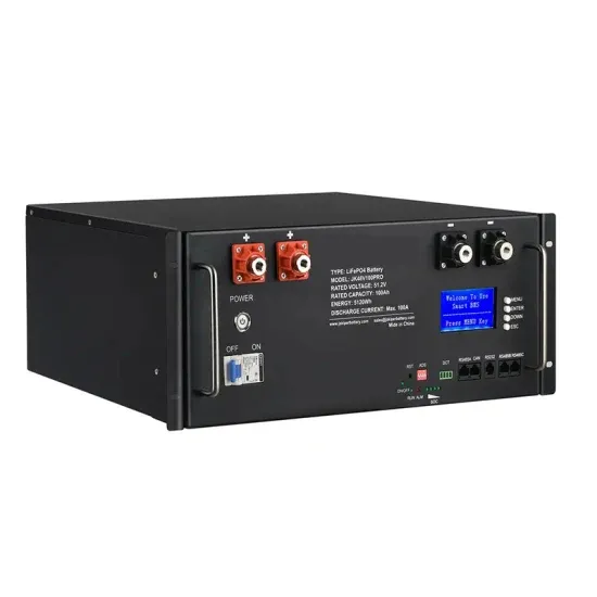
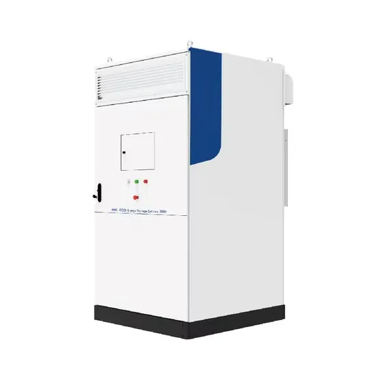
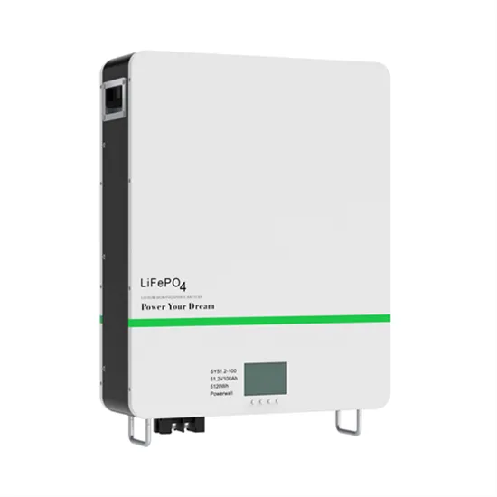
Technological advancements are dramatically improving industrial energy storage performance while reducing costs. Next-generation battery management systems maintain optimal operating conditions with 45% less energy consumption, extending battery lifespan to 20+ years. Standardized plug-and-play designs have reduced installation costs from $85/kWh to $40/kWh since 2023. Smart integration features now allow multiple industrial systems to operate as coordinated energy networks, increasing cost savings by 30% through peak shaving and demand charge management. Safety innovations including multi-stage fire suppression and thermal runaway prevention systems have reduced insurance premiums by 35% for industrial storage projects. New modular designs enable capacity expansion through simple system additions at just $200/kWh for incremental capacity. These innovations have improved ROI significantly, with commercial and industrial projects typically achieving payback in 3-5 years depending on local electricity rates and incentive programs. Recent pricing trends show standard industrial systems (1-2MWh) starting at $330,000 and large-scale systems (3-6MWh) from $600,000, with volume discounts available for enterprise orders.