Mar 22, 2016 · In this post we offer an introductory overview of regenerative drive operation (also referred to as "Active Front End" or "AFE"), covering the basic
Apr 22, 2019 · Two-stage inverters composed of the front DC-DC stage and the rear DC-AC stage are broadly employed for the current tracking. Structures vary according to the different control
Aug 1, 2022 · The model includes the PV arrays, front-end Boost converter, and rear-end inverter with output LCL filter. The impedance modeling of the PV inverter is derived at different
May 11, 2022 · This reference design is a three-phase inverter drive for controlling AC and Servo motors. It comprises of two boards: a power stage module and a control module.
May 5, 2016 · I am working on a two-stage non-isolated photovoltaic grid-connected inverter, with a boost circuit in the front stage and an inverter circuit in the back stage. I use two interrupts in
Principle of the circuit diagram of the rear stage of the high-frequency inverter The basic function of the rear stage circuit is to invert the high-voltage DC boosted by the front stage into AC.
1, the SCI booster (front stage) and DC-link inverter (rear stage) are connected in cascade between VS and Vo . The main function of the front stage is to obtain a step-up voltage of 4V
Jan 17, 2024 · The inverter stage is the "muscle" of the drive – a power electronics block that provides the regulated, conditioned power directly to the motor, driving it in the manner
Jan 4, 2024 · Our study provides a comprehensive analysis and classification of matrix-integrated isolated single-stage MF/HF AC-AC converters, DC-AC inverters, and AC-DC rectifier
2.1 Power Part: As in the power part of Fig. 1, the SCI booster (front stage) and DC-link inverter (rear stage) are connected in cascade between VS and Vo . The main function of the front
Jun 15, 2024 · In this paper, a single-stage alternative current (AC)-AC SST solution without bulky energy storage elements is presented. The front-end rectifier (FER) and rear-end inverter
Mar 27, 2024 · ABSTRACT This paper proposes a single-stage bridgeless isolated AC-DC power factor correction (PFC) topology, and this topology can realize the function of step-up and the
Apr 1, 2023 · ABSTRACT This technical white paper explores key system trends, architecture, and technology for traction inverters. The devices and technologies used to enable traction
Oct 18, 2023 · AC–DC converter has the advantages of high power density, stable output, easy to control, etc., and is widely used in many industrial fields. In this paper, the two-stage isolated
About this item This product is a high-power sine wave inverter board, which can be used for solar inverter conversion, modified wave inverter to sine wave inverter, high frequency square wave
Isolated AC-DC solid-state transformers widely use the front and rear multi-stage cascade structure of the bidirectional converter. Due to the difference in the control bandwidth of the
Apr 25, 2013 · The instantaneous output power of two-stage single-phase inverter pulsates at twice the output frequency, generating the second harmonic current (SHC) in the front-end DC
Principle of the circuit diagram of the rear stage of the high-frequency inverter. The basic function of the rear stage circuit is to invert the high-voltage DC boosted by the front stage into AC.
Mar 14, 2024 · Abstract AC–DC converter has the advantages of high power density, stable output, easy to control, etc., and is widely used in many industrial fields. In this paper, the two
Oct 1, 2023 · The front stage of the two-stage photovoltaic inverter adopts boost switching converter to realize maximum power tracking. The rear stage realizes sine wave current
Aug 19, 2025 · Multilevel topologies in PFC/Inverter Stage Three level topologies keep the switching voltage to half of a 2-level converter which improves overall EMI Multilevel topology
Jan 21, 2025 · Explore the exciting innovations in solar inverter technology, from AI-powered performance optimization and advanced battery storage to improved efficiency and smart
The inverter stage of the Power Inverter is a key step in converting rectified DC power into AC power. This stage achieves precise control of the output waveform by using high-frequency
The front stage of the AC/DC converter is a power factor correction circuit, which can improve the power factor and reduce grid-side current harmonics. Its performance affects the utilization of grid energy and control effect of the rear-stage DC/DC converter. Current research on PFC circuits mainly focuses on Boost and its improved circuits.
With the continued development of the new energy vehicle industry, two-stage isolated AC/DC converters are widely used because of their simple topology and easy control characteristics. In this study, we investigate the front-stage Buck power factor correction (PFC) converter and rear-stage full-bridge converter.
In summary, Cf = 100μF. The two-stage AC/DC converter control strategy is illustrated in ( Fig 6 ). Fig 6. Control strategy of two-stage AC/DC converter. The front-stage PFC circuit adopts a PI double-closed-loop control strategy [ 23 ]. The output voltage, input voltage, and input current were collected as the control variables.
Competing interests: The authors have declared that no competing interests exist. With the development of power electronics technology, high efficiency, high power density, and wide voltage range of AC/DC converter using two-stage circuit structure have become the industry research hotspot.
Three-phase inverter reference design for 200-480VAC drives (Rev. A) This reference design realizes a reinforced isolated three-phase inverter subsystem using isolated IGBT gate drivers and isolated current/voltage sensors.
The output of an inverter control MCU is 3.3-V PWM signal. This has to be converted into a 10-mA current signal. Multiple circuit configurations can be implemented for this conversion. TIDA-010025 has provisions on board to evaluate each of the input drive methods.
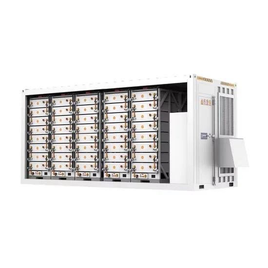
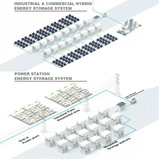
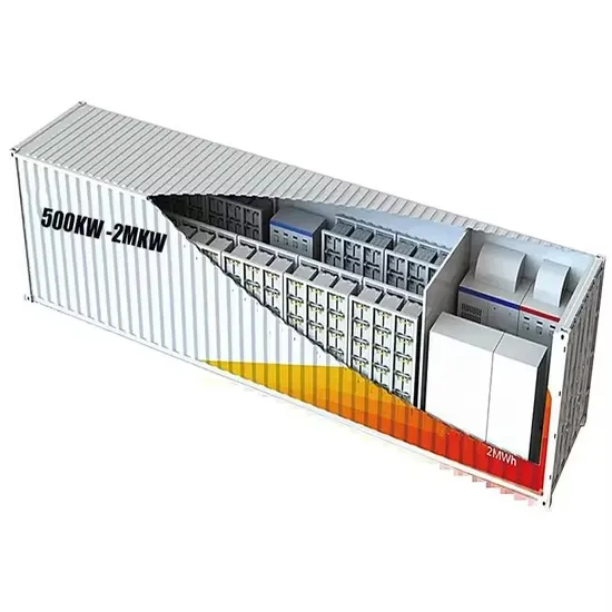
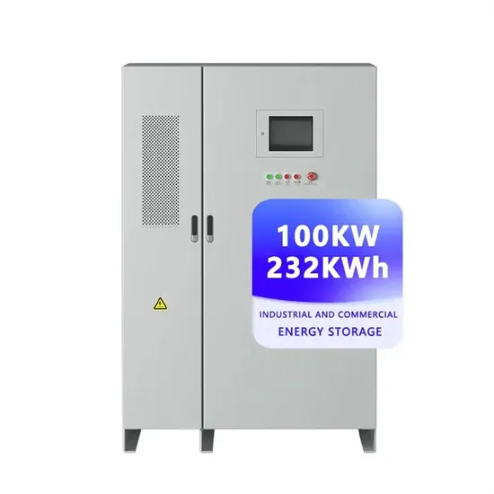
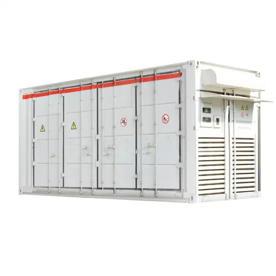
The global industrial and commercial energy storage market is experiencing explosive growth, with demand increasing by over 250% in the past two years. Containerized energy storage solutions now account for approximately 45% of all new commercial and industrial storage deployments worldwide. North America leads with 42% market share, driven by corporate sustainability initiatives and tax incentives that reduce total project costs by 18-28%. Europe follows closely with 35% market share, where standardized industrial storage designs have cut installation timelines by 65% compared to traditional built-in-place systems. Asia-Pacific represents the fastest-growing region at 50% CAGR, with manufacturing scale reducing system prices by 20% annually. Emerging markets in Africa and Latin America are adopting industrial storage solutions for peak shaving and backup power, with typical payback periods of 2-4 years. Major commercial projects now deploy clusters of 15+ systems creating storage networks with 80+MWh capacity at costs below $270/kWh for large-scale industrial applications.
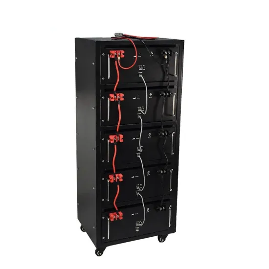
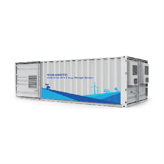
Technological advancements are dramatically improving industrial energy storage performance while reducing costs. Next-generation battery management systems maintain optimal operating conditions with 45% less energy consumption, extending battery lifespan to 20+ years. Standardized plug-and-play designs have reduced installation costs from $85/kWh to $40/kWh since 2023. Smart integration features now allow multiple industrial systems to operate as coordinated energy networks, increasing cost savings by 30% through peak shaving and demand charge management. Safety innovations including multi-stage fire suppression and thermal runaway prevention systems have reduced insurance premiums by 35% for industrial storage projects. New modular designs enable capacity expansion through simple system additions at just $200/kWh for incremental capacity. These innovations have improved ROI significantly, with commercial and industrial projects typically achieving payback in 3-5 years depending on local electricity rates and incentive programs. Recent pricing trends show standard industrial systems (1-2MWh) starting at $330,000 and large-scale systems (3-6MWh) from $600,000, with volume discounts available for enterprise orders.