What does a typical Base system installation look like? How does the Base system interact with the generator interlock on the main panel? How do I connect my battery to my home WiFi
Our company has developed an integrated design of distributed base station power supply system for a variety of installation environments such as corridor, shaft, and outdoor environment. The
Dec 7, 2022 · A complete station service supply and distribution system should be provided to furnish power for station, dam auxiliaries, lighting, and other adjacent features of the project.

The power distribution cabinet (box) is divided into a power distribution cabinet (box), a lighting distribution cabinet (box), and a measurement cabinet This paper reviews the main concept
Aug 8, 2025 · Your base station should come supplied with a power supply cord to connect the male IEC connector on the PMU to the local AC supply. The pins of the IEC connector on the
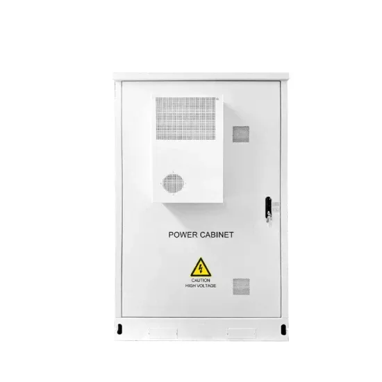
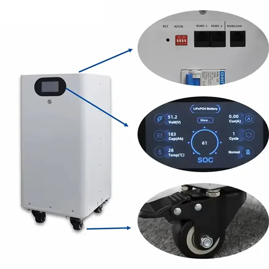
The base station power cabinet is a key equipment ensuring continuous power supply to base station devices, with LLVD (Load Low Voltage Disconnect) and BLVD (Battery Low Voltage
Mar 23, 2020 · Remove the water panel to access the back-side of the "T" fitting (3/4" female fitting) for connection. We recommend attaching a flex-ible stainless or black-poly hose from
Feb 20, 2025 · 5. Sensor and Network Connection: The base station will automatically connect to an ISN sensor within range. The base station will establish a connection to nearby mobile
This section describes how to connect external power cables to the cabinet. The external AC power cables can be laid out in overhead or underfloor cabling mode. The external DC power
Aug 11, 2018 · ng to connect to the Gateway. Base Stations Base Stations are intended for deployments that extend over a la. e area (such as a city or a large campus). The Base
• On Concrete At each corner, utilize four 3/8" compres- sion bolts or threaded rod set in the concrete on 11.75" centers for through- hole mounting of the Powerhouse base. • On Wood At each corner, utilize four 3/8" bolts or lag screws on 11.75" center for through-hole mounting of the Powerhouse base.
Remove the local area Ethernet connection and connect an Ethernet patch cable between the PC and the base station. You can use either straight through or crossover Ethernet patch cable with the current base station firmware. Click Start > Settings > Control Panel. Double-click Network Connections.
The DC supply to the reciters is via the system control bus ribbon cable. The connections between modules at the front of a single 50W base station are shown below. The PA is powered by a direct connection from the PMU. The reciter is powered from the PMU via the subrack interconnect board and system control bus ribbon cable.
If an external reference is required, enable the external reference “Absent” alarm (Configure > Alarms > Control). Use a 50: coaxial cable (RG58 or RG223) to connect the external reference to the base station’s external reference frequency input. You can daisy-chain up to eight base stations using F-junctions.
Use a 50: coaxial cable (RG58 or RG223) to connect the source to the base station’s 1PPS input. You can daisy-chain up to eight base stations using F-junctions. We recommend that the cable length between the first and last load is kept to a minimum. This will reduce any propagation variation between base stations.
Single base stations need a control connection to their site controller. A single base station interfaces to the site controller in the same way as the master base station in a trunked channel group. Select Configure > Network Interfaces > Trunking to configure this. You can program a receiver with the same configuration as a reciter.
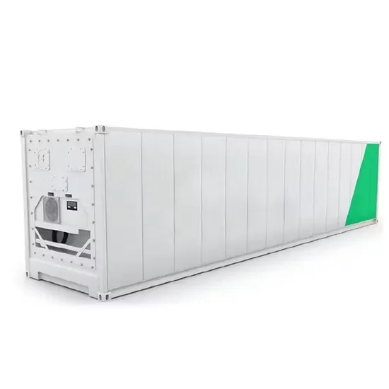
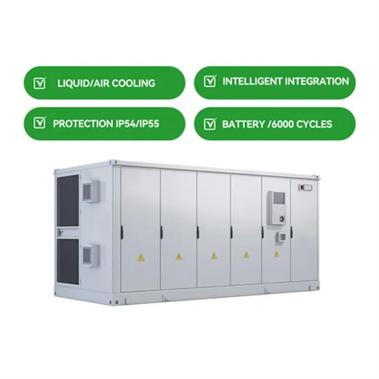
The global industrial and commercial energy storage market is experiencing explosive growth, with demand increasing by over 250% in the past two years. Containerized energy storage solutions now account for approximately 45% of all new commercial and industrial storage deployments worldwide. North America leads with 42% market share, driven by corporate sustainability initiatives and tax incentives that reduce total project costs by 18-28%. Europe follows closely with 35% market share, where standardized industrial storage designs have cut installation timelines by 65% compared to traditional built-in-place systems. Asia-Pacific represents the fastest-growing region at 50% CAGR, with manufacturing scale reducing system prices by 20% annually. Emerging markets in Africa and Latin America are adopting industrial storage solutions for peak shaving and backup power, with typical payback periods of 2-4 years. Major commercial projects now deploy clusters of 15+ systems creating storage networks with 80+MWh capacity at costs below $270/kWh for large-scale industrial applications.
Technological advancements are dramatically improving industrial energy storage performance while reducing costs. Next-generation battery management systems maintain optimal operating conditions with 45% less energy consumption, extending battery lifespan to 20+ years. Standardized plug-and-play designs have reduced installation costs from $85/kWh to $40/kWh since 2023. Smart integration features now allow multiple industrial systems to operate as coordinated energy networks, increasing cost savings by 30% through peak shaving and demand charge management. Safety innovations including multi-stage fire suppression and thermal runaway prevention systems have reduced insurance premiums by 35% for industrial storage projects. New modular designs enable capacity expansion through simple system additions at just $200/kWh for incremental capacity. These innovations have improved ROI significantly, with commercial and industrial projects typically achieving payback in 3-5 years depending on local electricity rates and incentive programs. Recent pricing trends show standard industrial systems (1-2MWh) starting at $330,000 and large-scale systems (3-6MWh) from $600,000, with volume discounts available for enterprise orders.